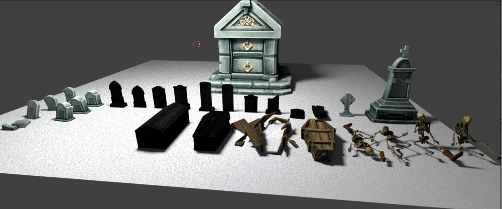
LOZ Project – Overworld Setup Documentation Screen Shots Included in this Document…
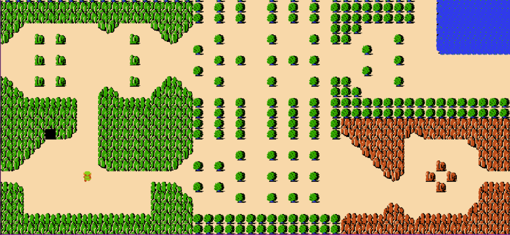
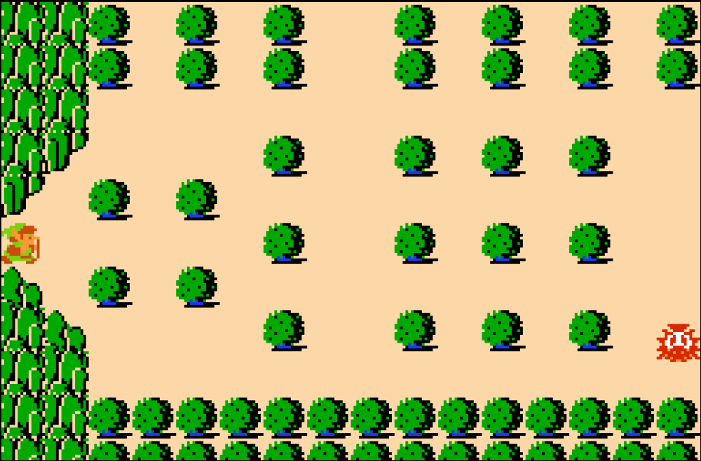
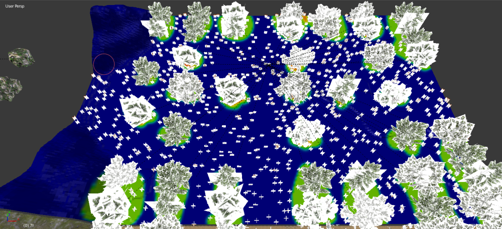
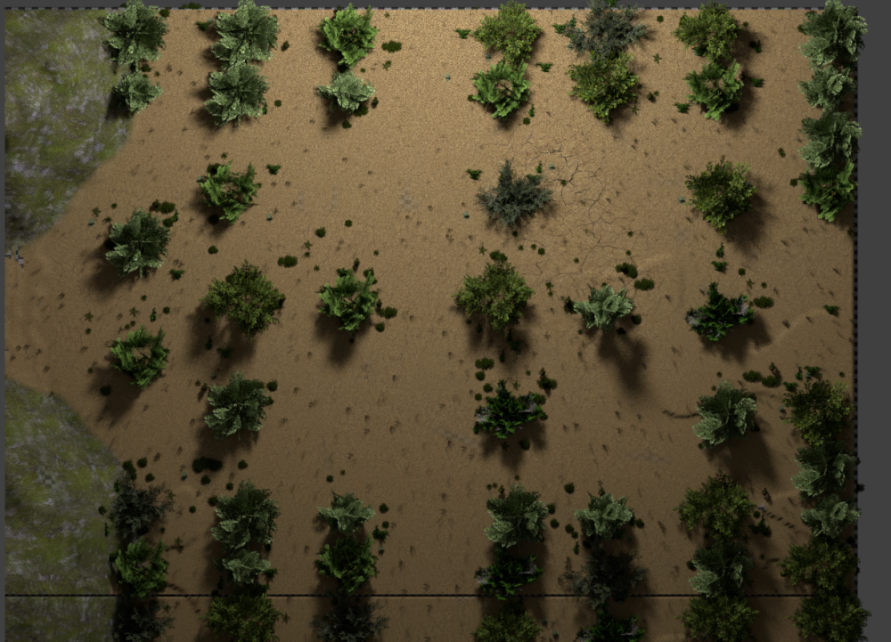
Exporting a massive map from L3DT. This is the program that I took the B&W map I made from an actual game map and hand sculpted the mountains and such to keep the definition of the outline of each screen. This map has an extra screens worth of terrain around the edges, so it is 18 by 10 screens. It was interesting getting the output file from L3DT to the proper size to keep the aspect ratio of the overworld.
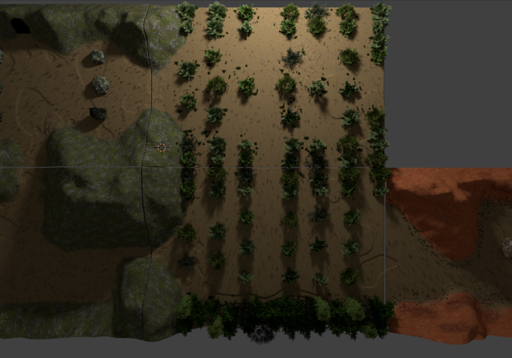
Each in game screen is 16 tiles by 11 tiles. This is a 1.45:1 ratio. I have the individual screens sized out at 512 * 353 pixels, which keeps the 1.45:1 ratio.
18 screens across is 9216 pixels, 10 screens high are 3530 pixels. I am hoping that this size will allow me more detail in the individual screens, the dips and detail I wanted to be much finer than it was when I tested motion in Unity. The map I am using now is nearly four times larger than the original I had made.
I then split the main image up into the individual screens (180 of them!) using the site http://imagesplitter.net/.
Now the individual screens can be loaded into Blender for editing.
Importing an image into Blender as a plane
The image to load will be the original screen texture file. The material we create will be called screen Original.
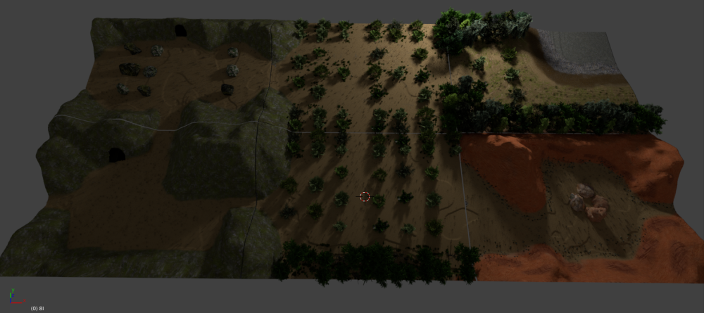
Resize the plane that was imported. Set the location to 0,0,0. Keep the same scale 1.45:1, I went with 145 X 100 units. Apply the scale with CTRL+A while the plane is selected.
Set the Render mode to Cycle Render.
Change to TEXTURE View and you can see the image on our plane.
Next, we need to subdivide the surface. Press TAB to change to EDIT MODE. Select “Subdivide” from the sidebar on the left, under the “Tools” tab.
Edit Mode, 45 Cuts, Object Mode, Edit Mode, 4 Cuts. Leaves with 105,800 Tris for the screen.
Rename our plane to the screen ID.
Setup the material for the imported plane
Original Game Texture.
Since we imported the Original Texture version of the image, this material is already setup and good to go for use as the original texture.
Displacement Texture (The Heightmap)
To make the displace texture available, we need to add a Displace modifier.
Now go to the TEXTURE tab and create a new DISPLACE texture.
Add a New image. Find the heightmap. Name the displacement texture screen HM.
Under IMAGE MAPPING, set the Extension to Clip.
Setup the Displacement Modifier
Because we setup the new texture as a Displace, it has automatically populated in the modifier.
Set the Coordinates for the texture to UV, strength to 100
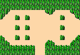
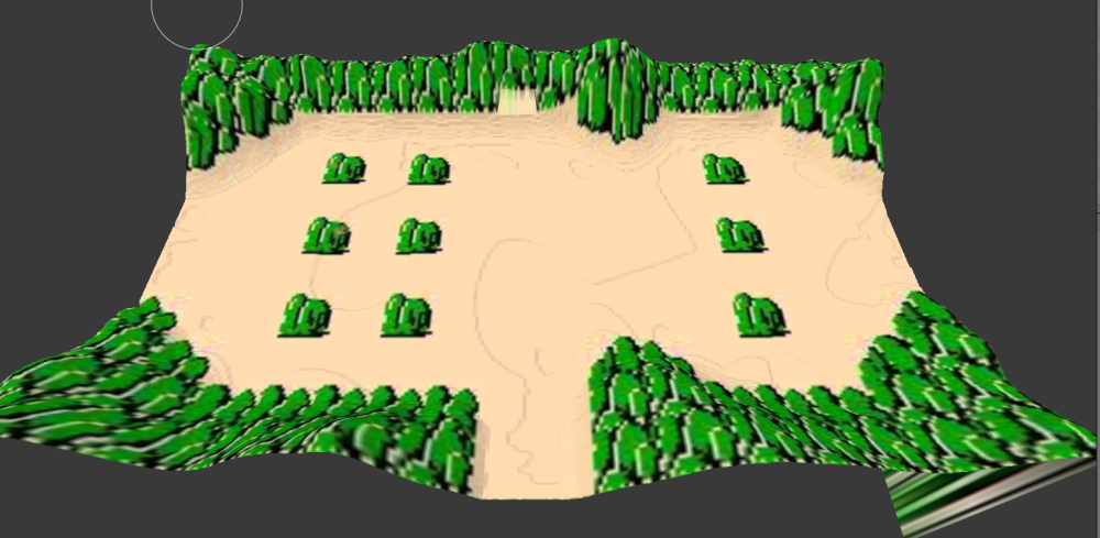
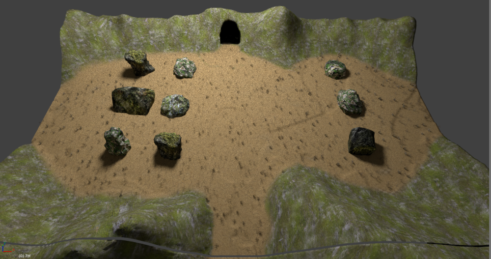
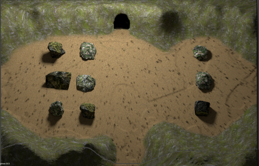
The imported screen. (No Texture)
Texture Applied
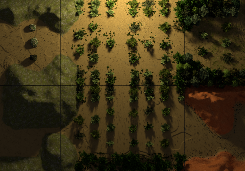
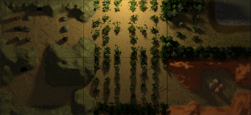
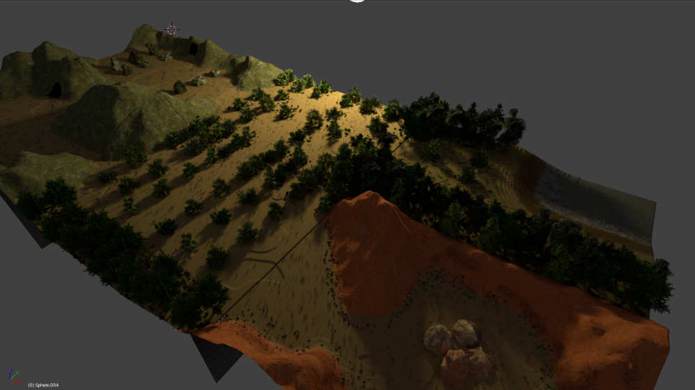
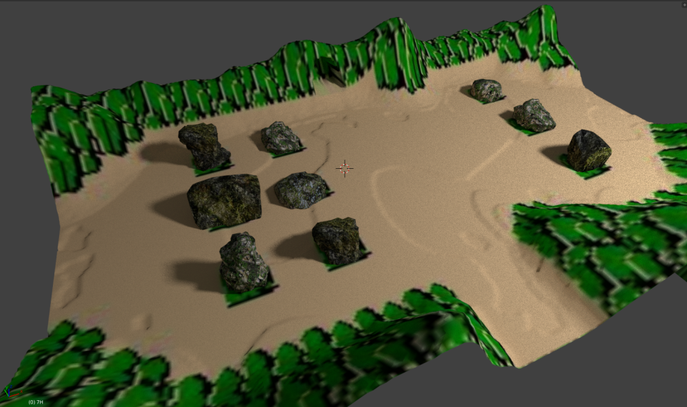
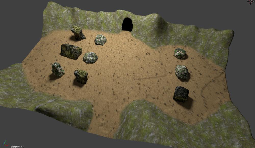
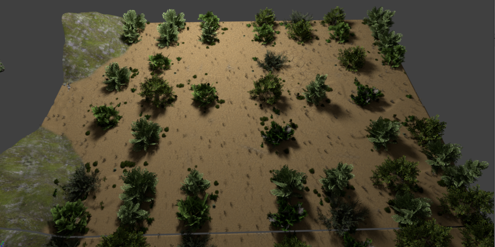
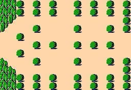
We will go ahead and texture with an original map screen initially, to make certain things are lined up and that when we place brush and trees, cut out caves, etc. we will have things in the right spot.
Painting the High-Resolution Textures
Setup the new Texture
In UV EDIT MODE, create a new texture image.
Name this screen High Res. Set the resolution to 8192 X 8192. Set it so you can see a UV grid.
Create a new material
We need to setup a new material for our high res texture.
Name the new material screen High Res.
Setup the node as a Diffuse BSDF, select the newly created screen High Res image with the UV Squares as the image. See below for node view.
To get this new High Res material to show as the current texture, you will need to use the minus sign to remove the screen Original material. It can be added back on later.
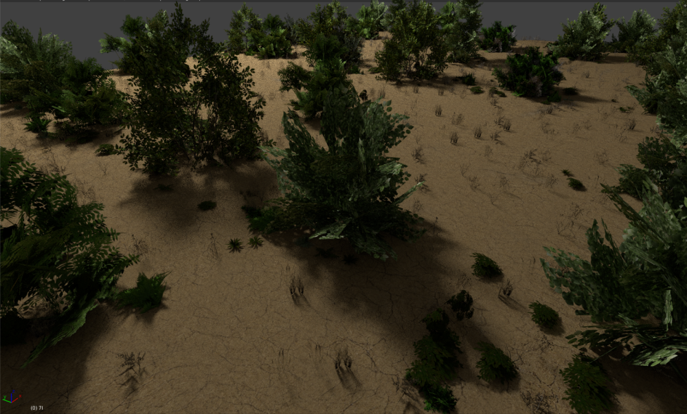
Adding the brush textures
Enter Texture Paint Mode.
Under Tools, on the left bar, there is a TEXTURE section. Add a new one.
If you click the “New” button, a brush texture will be created. Go to the TEXTURE tab to edit it.
Rename the brush from Texture to what you need it to be. Press “Open” so we can navigate to the image we need.
Now that the bush has been made, click the area in Textures, under the tools and select the bursh. You can now paint the texture directly onto the model.
Set to random for good mixing. No need for tiled texture!
If it is not painting on angles for some reason, you need to set the scaling! A step was forgotten!!
Fwwwwwww
Finish your painting.
Save the image so the texture you just painted is saved over the UV Squares.
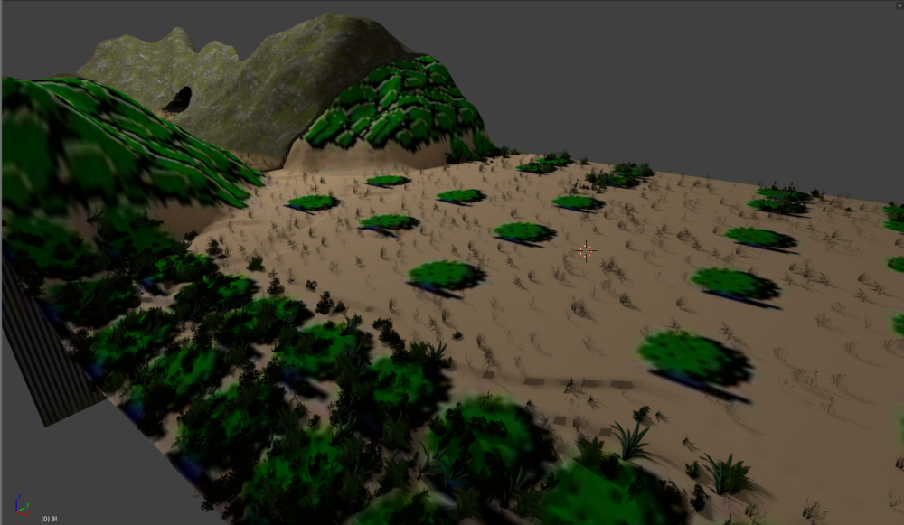
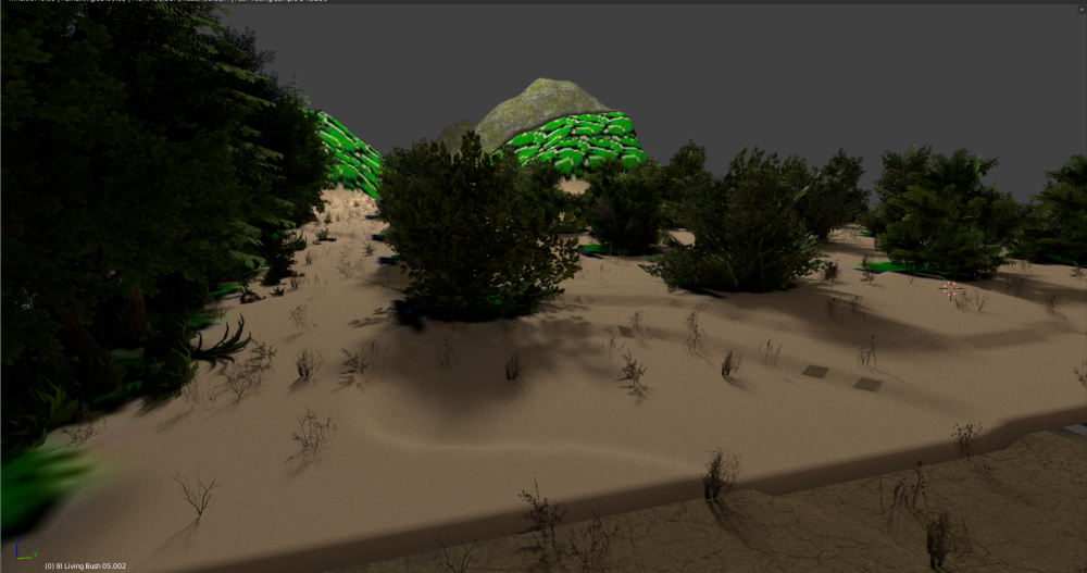
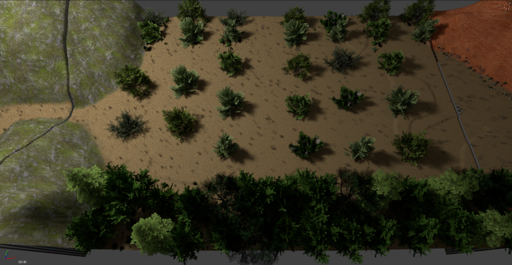
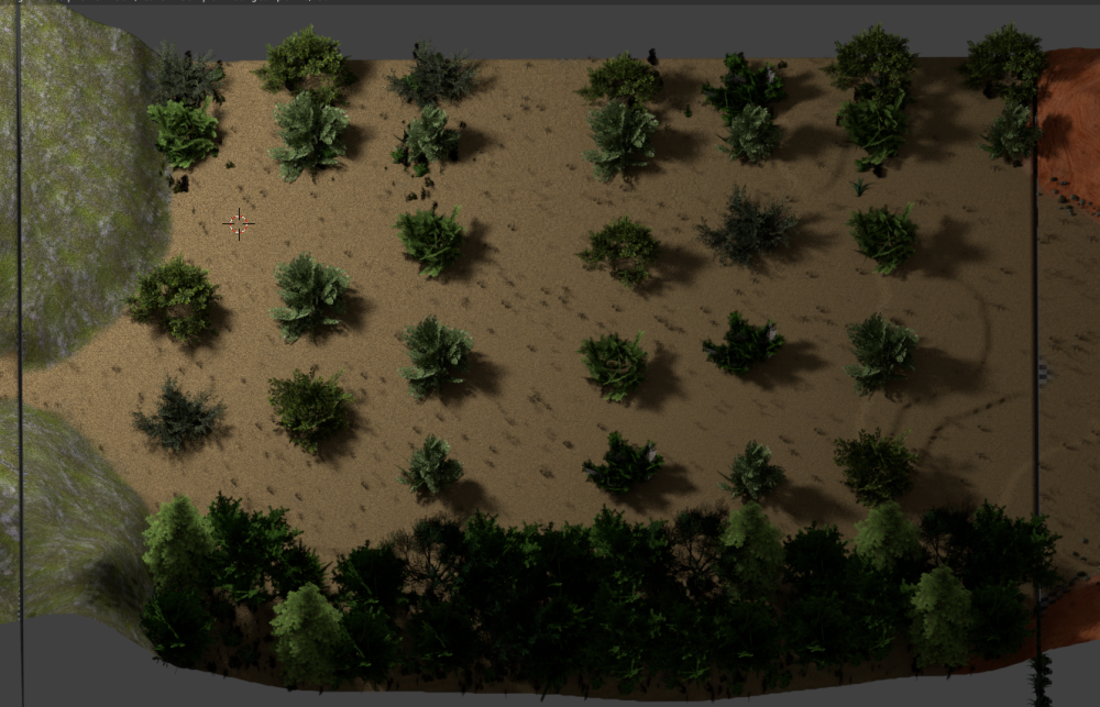
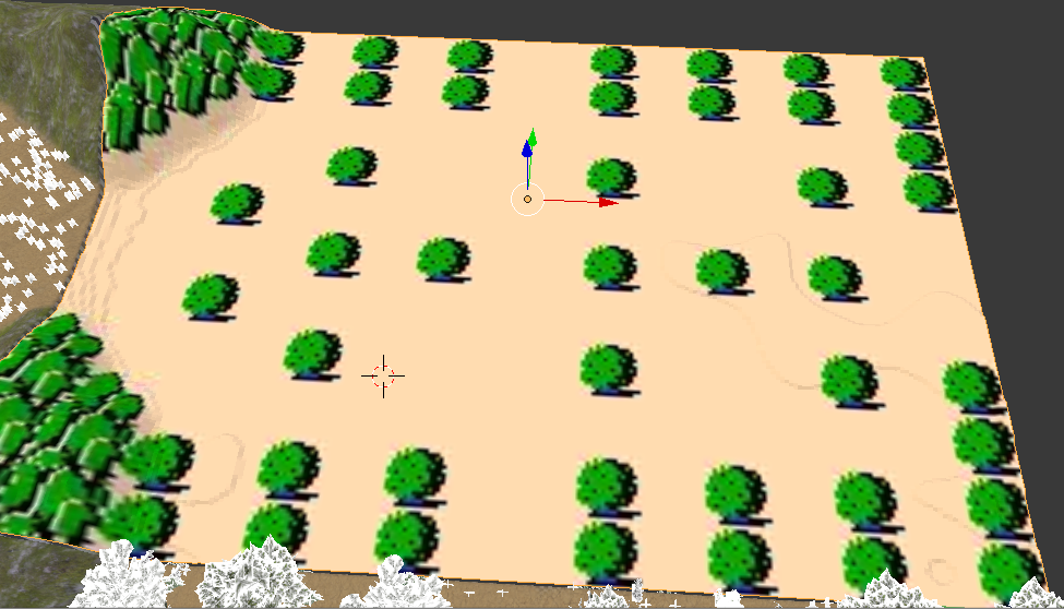
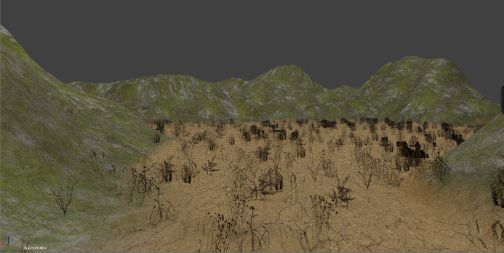
Adding Grass (As Fur!)
Make your grass
On a new layer, we are going to create the grass that will be used in our particle groups.
Create a pair of planes and cross them perpendicularly intersecting. Join the two objects, normalize the scaling and unwrap it.
Set the orgin to the base of the object. In the UV editor, open a grass blade to use.
Get it so both planes cover the grass properly, centered. Rotate as needed.
Setup the node for the material as follow:
I have saved five types of dry grass to layer two.
Rendered
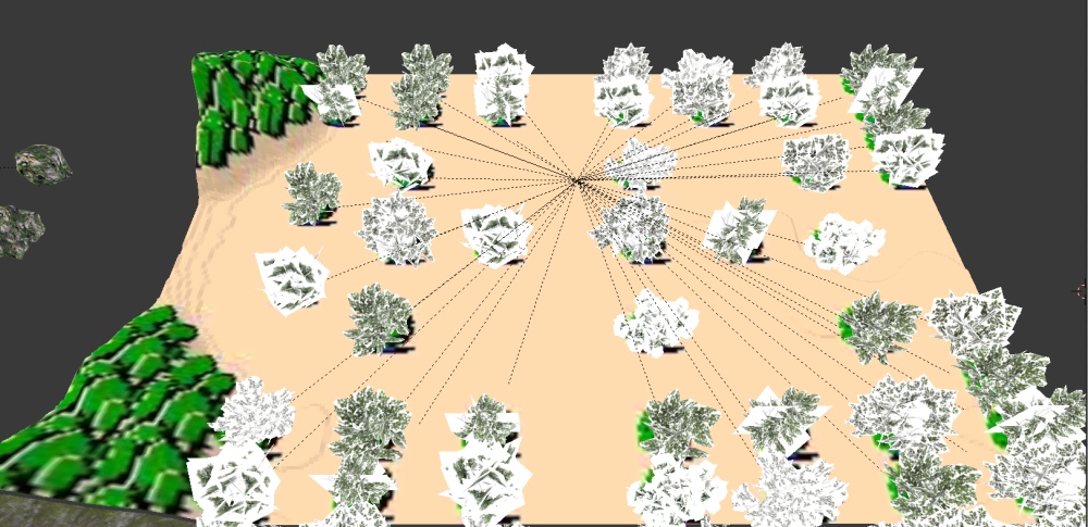
Group all of the objects together. Select them all and press CTRL+G. This will highlight them in a green border. Go under the Object tab and you will see a new group.
Name the group what you need it to be.
Select where the grass goes
Edit Mode, select the area that we want to paint with grass.
Under the Object Data tab, the Vertex Groups, create a new group and give it a name.
Go into weighted paint mode and you can see how much of the particle will go where. Red is much, Blue is None, green and yellow are in between.
Setup the Particle System!
Under the particle tab, after selecting the terrain, you will want to setup your new system.
Name is what you want.
Grass tends to place sideways. Need to set Rotation and put Random to zero and Phase to 0.500.
Check the Physics. If things seem too small, make certain things are as follows:
Next we need to tell the system what objects we will be using for the particles.
Under Render, from the particles tab, select the Group button and select our grass group we created on layer 2.
Now we tell it where to place the objects. Under the Vertex Groups section, select the vertex group we created earlier. This is for DENSITY.
Now the grass is placed only where we want it!!